INSTALLATION OVERVIEW
this is a DIY guide explaining how to replace your dash indicator lights with blue LEDs.
this was done on a 1993 Honda Accord LX, other years and trim levels may be a
little different. READ THE ENTIRE GUIDE BEFORE ATTEMPTING!! things i say in the
middle of the guide u might need to know before u start- i wrote this guide a few weeks
after i did the swap myself, so i had to redo everything inside my head :-p
this mod requires you to remove and take apart your guage cluster- only do it if you are
confident in your abilities, i have heard of people breaking theirs and needing to get a
new one. WHEN TAKING IT APART, use a black marker and MARK every screw or thing you
disconnect, because after a while, its confusing where everything went. before u
take something off, it would be a good idea to circle all the screws u took out and leave
them aside so they dont get mixed up. be careful, things in the cluster are
delicate, and dont rush and u should be fine. Please send any questions or comments to the
email addy listed above :) |
PARTS NEEDED
1. enough LEDs for all of your indicators- i needed 11
--- i used 3.3 volt, 20milliamp, 5millimeter ultra bright, focused blue LEDs.
2. a resistor for each LED- explained inside of the guide.
3. transparent thin blue plastic that diffuses light well (cut up a blue flexible binder
from officemax or something)
4. needle nose pliers
5. phillips head (+) screwdriver
6. tranparent "scotch" tape
7. razorblade
8. soldering iron and solder
9. dremel
10. knowledge of how to use all the tools listed above :) |
NOTICE AND DISCLAIMER
This is a DIY guide to be used as a guide to help you do thigns on your own- the author is
NOT responsible for any damage done due to anything mentioned in the guide. do this
at your own risk. blue indicator lights may be illegal in some states and may make
your car fail inspection. be sure to check on this before proceeding.
NOTICE: i ran into problems with resistors and LEDs that burned out- i mention
everything in the guide, and if u follow what i say i dont think you will have the same
problem. the only thing that i still dont know for sure is the polarity of each
connector on the board- standard bulbs can be installed in either direction, but LEDs need
to be hooked up to the correct + and - locations, and i dont know which side of each
connector on the board is which. hooking up an LED backwards wont hurt it, so you
need to install the LEDs any which way at first, put the cluster back into the car, and
see which ones dont light up. pull the cluster back out, take it apart again, and reverse
the LEDs that didnt light up. put the cluster back into the car, and everything
should work fine (unless you screwed somethign else up and there is some other problem :)
) If someone successfully completes this DIY mod, i would really appreciate if they could
get back to me and i will explain to them how to check the polarity, so i can add the
information to this guide to save other people from doing the extra work of taking the
cluster back out again. |
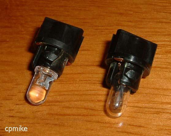
ALTERNATIVES
you cant leave the original OEM bulbs in and just change the colored filter (second and
third pics down)- the stock bulbs are yellowey and i assure you that when u put it all
back together if you do it that way, the color will NOT be what you want. The only
way to get that strong, deep blue color is to use LEDs, but if you dont feel like you are
able to do the LED install, you can find blue size 74 (often called "dash indicator
lights" or something to that effect) bulbs, and all u gotta do is open everything up
and replace the stock white bulbs with the new blue ones, and also replace the colored
filter. thats it- no cutting or soldering or resistors. but know that if you
do it this way, the color will be washed out and lighter, like a lighter blue color (see
the pic all the way at the bottom!). also its kinda hard to find size 74 bulbs. but
do it either way :) |
 |
to get the guage cluster out u gotta remove the black trim from ur
dashboard/radio area. u need to pull ur air vents and buttons out (like the
hazard and rear defrost buttons) and take all the screws out. refer to a guide to do
this.
once u got the cluster out, remove the clear plastic front by unclipping it from around
the sides of the cluster. pull off the black trim piece, revealing the bare guage
faces. (to do this u need to pull the little rubber knob thing off the end of the odometer
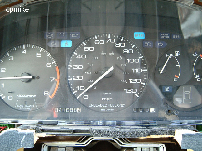
reset button). REMEMBER where ur gas meter is!! its the only meter that
retains its position when the car is off.
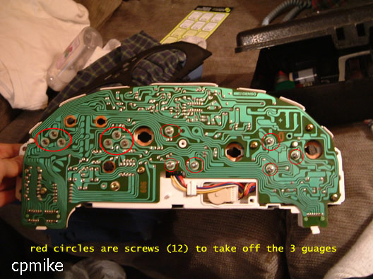
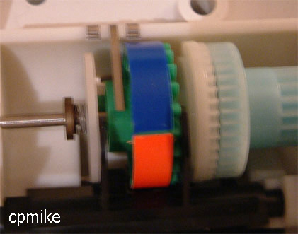
flip the cluster over and remove the white back piece, dont remember how many screws there
are, until u see whats in the pic to the left. i circled the 12 screws to take out-
there are 2 different kinds... take them all out, but dont mix up where they went!
as u unscrew them, support the guage from the underside, cuz it will fall out
if u dont. (the speedo is connected by wires, so itll be loose, but wont come all the way
out) |
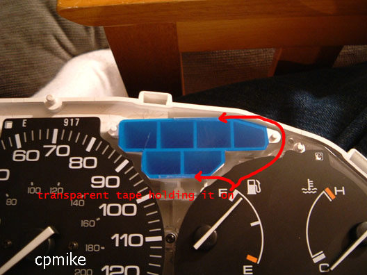 |
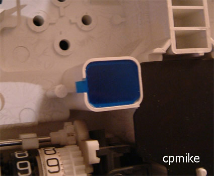
flip it back over, and ull find 3 colored filters- a little one where the
gas light is, and 2 bigger ones on top of either side of the speedo. this pic is of
the top right one- peel off the old filter (held on by a little adhesive). get
one of those flexible blue plastic binders from officemax and cut out a shape to match the
old filter. try to use a plastic that will diffuse light... like if u hold it up to the
light, u cant really see thru it, besides a big splotch of blue light- if u can clearly
see thru it, try to find a better one.
to hold the new filter on, use a little transparent tape on the top and bottom edge-
somewhere that u wont see when its all back together. on my LX one of the spots
doesnt actually have a light, u can use that space to put the tape on. be creative. |
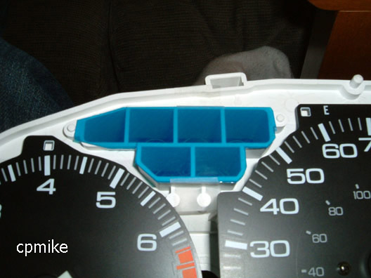 |
same with the left side. this pic makes the blue plastic look really
clear- and thats because it is. i took these pics before i found a better blue plastic. |
 |
this was my own personal touch, i put blue electrical tape over the green
part of the "maintenance required" wheel, so itll show up blue instead of green.
this is totally optional. |
 |
"low gas" light- u gotta cut out a shape that u can push into
the hole and have it fit snugly, so it doesnt pop out... if u wanna use tape or a little
glue, be my guest. |
 |
look back at the back of the cluster, at the big circuit board.
theres a couple screws still holding the board down- take those out and remove the board
to get to everything underneath. to the top of the cluster is another small circuit
board- thats the one we are interested in. twist all the little black knobs to the
left and pull them out- they are the bulb holders - and unscrew the circuit board.
lay everything besides the bulb holders and the small circuit board.
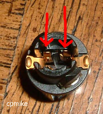
this is the inside of the bulb holder w/ bulb removed. the idea is gonna be to get
each of the LED leads to touch the metal connections inside the bulb holder. more
detail a couple pics down. |
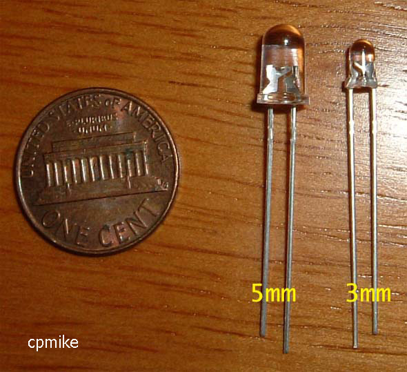 |
LED size comparison. u can use the 3mm kind if thats what u got, but
the 5mm ones are the same exact size as the original bulbs so thats what i went with.
i used 3.3 volt, high intensity blue LEDs that i got off ebay for pretty cheap.
you need matching resistors- for a 20mA 3.3volt LED u should use like a 600
ohm resistor for each LED... use this LED
CALCULATOR (the "single led" section) to find out what resitor u need that
matches the specs of the LEDs u got. add some to the ohms to be safe, the only thing it
will do is make the LED SLIGHTLY dimmer. like if it said use a 470, try a 600. supply
voltage is technically 12volts. my LEDs were 20 Milliamps and 3.3 volts.
also, resistors come in different wattages. i used 1/2 watt resistors because thats
what i had alot of, but the LED calculator says that you should be fine with 1/4 watt
resistors (which are a little smaller- check the packaging before you buy) |
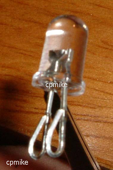 |
to get the LED to fit in the bulb holder, u gotta bend the leads like
this, to match the shape of the original bulb. also to fit correctly, u need to
separate the leads from each other just a tad. you will see what i mean. |
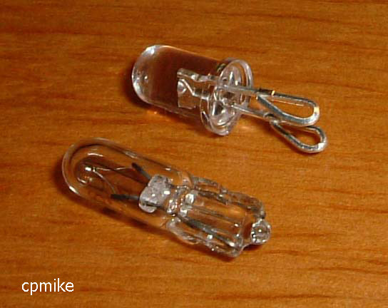 |
comparison between a prepared 5mm LED and the original size 74 bulb.
if you did this w/ 3mm LEDs, it would be the same process. |
 |
another comparison, showing a bulb on the right and a LED on the left.
not a bad, ey? |
 |
my LED's were focused- like they were blinding from straight on, but from
an angle, you could hardly see it. if you have this kind of LED (which i suggest u
should) u need to use a dremel and shave off the top of each LED, so its rough and flat.
this is a pic of a few completely done LEDs. |
 |
heres the more annoying part. each LED needs a resistor connected in
series with it... but the way this circuit board is, everything is a trace on the board,
and theres no way to fit a resistor in the bulb holder. it doesnt matter which side
the resistor is connected to- as long as how its hooked up is that NO current will be
allowed to go thru the LED without also going thru the resistor.
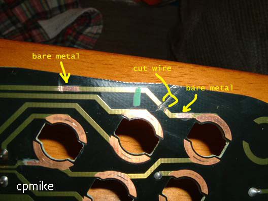
i used a razor blade to remove a section of the wire trace from the circuit board, and
used it to scrape off the clear green insulating layer from 2 sections on either side of
the cut i made, to reveal the metal trace underneath. make sure the scrapes are
close enough together for a resistor to fit, but not too close that everything is cramped.
this pic is an example of the first one i did, i show the other ones later. |
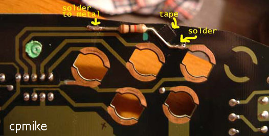 |
i taped over the cut just to be safe, and soldered a resistor to the 2
bare metal spots. what this does is effectively replace the wire trace that was on
the circuit board with a resistor.
this pic is of a 1000ohm, 1/2 watt resistor- which i later had problems with. like said
earlier, try like a 600ohm (or whatever the LED calc said + a little more), and u can use
a 1/4 watt if u want. so ur resistor might not be the same size, and will
probably have different color stripes on it. |
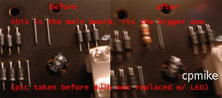 |
go back to the large circuit board - it has the "low gas" light
on it. if u follow the traces ull see that one of them goes along a metal jumper
wire. i unsoldered the jumper and replaced it with a resistor, so i didnt have to do
any cutting of wire traces.
sorry for the bad pic, but u can still see what i did. |
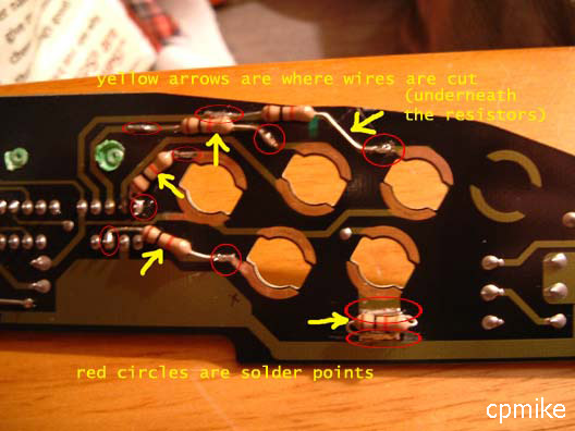 |
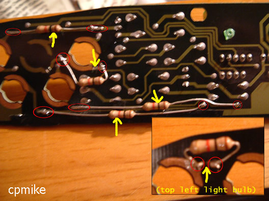
this is the right side of the small circuit board. the yellow arrows
point to where i made the cut in the wire trace (i usually cut underneath where the
resistor was gona be), and the red circles are where i revealed the metal and soldered the
resistor leads to the board. USE THE WIRE TRACES THAT I SHOW IN THIS PICTURE.
there is a reason for it, but i dont want to explain series and parallel circuit
theory. u have some leeway on where u actually make the cuts in the trace, but what
is shown on the left is recommended. a couple of these might be alittle unclear or
hard to understand from the pic... if u are having a hard time, ill draw a better pic for
you.
when ur done, make sure u go thru and make sure everything looks ok, nothing is touching
anything it shouldnt, and everything is soldered correctly. |
 |
this is the left side of the circuit board, and are all the cut and solder
locations. again, yellow arrow= cut in wire trace and red circle = where i soldered
the resistor to. a couple of these might be alittle unclear or hard to understand
from the pic... if u are having a hard time, ill draw a better pic for you.
when ur done, make sure u go thru and make sure everything looks ok, nothing is touching
anything it shouldnt, and everything is soldered correctly. |
.jpg) |
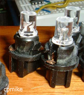
at this point, you should be pretty much done! put the small circuit
board back into the white plastic guage cluster and screw it in. put the LEDs thru
the holes and twist the each holder to the right to secure them (same as u took them out),
put the big circuit board back on, then rescrew the guages back in (caution- DONT tighten
the 12 screws too much! it will damage the circuit on the back of the guage- tighten
enough to securely hold the guage in place). put the black front bezel back on,
screw the white plastic cover onto the back, and pop the front clear lens on again.
if all went well, all ur lights should look like this pic :-D this pic is kinda
messed up, the glare messed the camera up, but u get the idea.
**READ NOTICE ON TOP ABOUT LED POLARITY** |