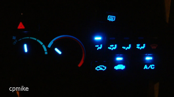
90-93 Accord Climate Control LEDage
by Mike Maset 2003 - aim: cpm1xe
linkage: accordtuner.com cb7tuner.com
accordracing.com
PARTS LIST
9 3mm LEDs
8 5mm OR more 3mm LEDs
1 white LED
10 resistors- see blurb below about finding correct rating.
non-solder perfboard of some sort to mount the LEDs to
extra wire
double sided foam tape for spacing/mounting
superglue (best stuff in the world)
screwdrivers / pliars / soldering iron / solder / wire cutters / etc
LED
RESISTANCE CALCULATOR Use the "single led" section of the above link to
calculate the required ohm rating for the resistors. use supply volts=14, and the LED drop
voltage and current are provided by the place u got the LEDs from. in my case, it was 3.3V
and 20mA. Use the "nearest 10% rated" value for your resistors. And if you have
a choice, get 1/2 watt resistors, not 1/4. just to be safe.
ISSUE OF WANTING DIFFERENT COLORS (other than blue)
only problem with a different color is that the buttons have pieces of blue
plastic behind each of the button faces... from the front, u can pop off each button face
(from the bottom edge with a small flathead screwdriver) and remove the blue plastic, but
that usually breaks the clips along the bottom edge of the button. this isnt visible once
the button face is put back on, and you would probably need to superglue the inside of the
button back down, so it wont pop off... but if ur happy with picking a different color,
then i guess u wouldnt mind making it permanent.
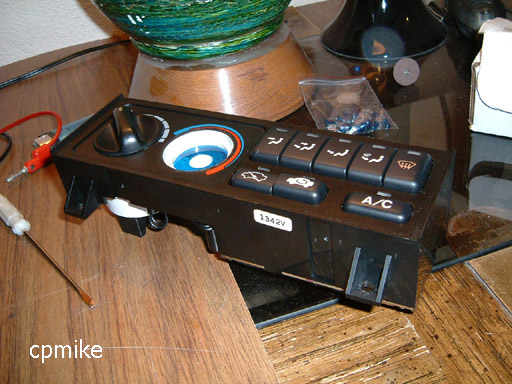 |
1 remove the climate control unit from the car by taking off the dashboard trim, then the 4 screws on the CC unit. u need to remove the temp knob and unscrew the temp assembly from the back of the CC. |
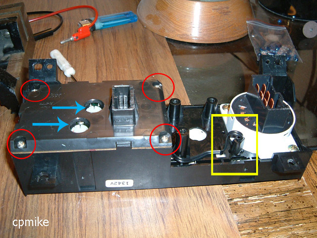 |
2 2 blue arrows are
the bulbs that illuminate the little pictures on all the buttons. take them out once
u remove the back cover, by removing 4 screws (red circles). |
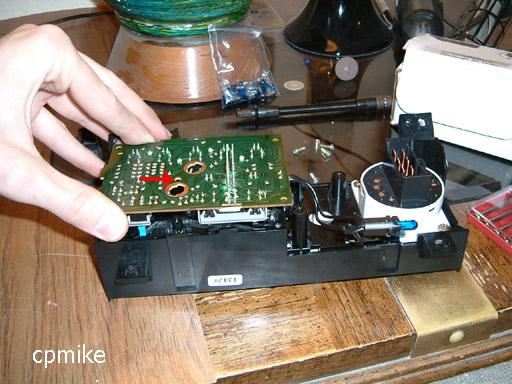 |
3 take out screw (red arrow) and pull off circuit board. its clipped to the buttons so pull hard till it pops off.. once it comes off, u will find 2 clear plastic prizm-type lenses on the inside, pull them both out. u wont need them anymore. |
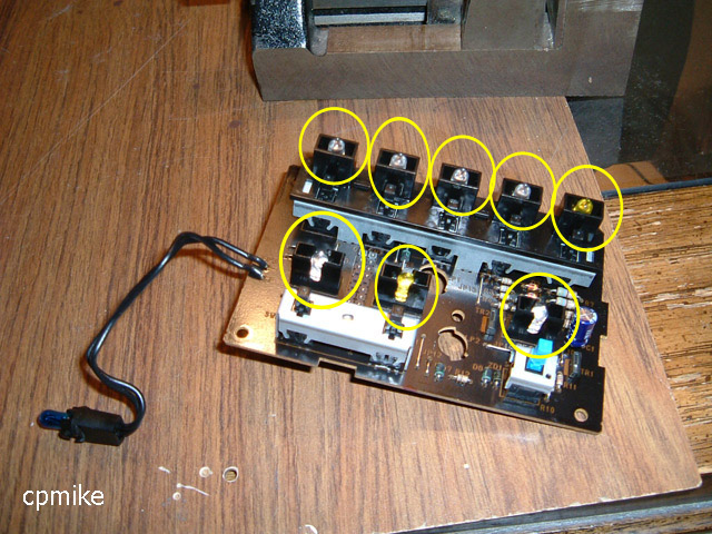 |
4 8 yellow circles are the indicator LEDs that u can basically just unsolder and solder ur own blue ones in. more details below. |
 |
5 these are the connections for the 8 LEDs- unsolder these and solder in new LEDs (below)- (+) is on the left and (-) on the right for all connections, besides the 2 bulb holes. |
 |
6 i soldered in some 3mm LEDs with shaved tops. u dont need resistors cuz this was setup to use LEDs stock. make sure the LED (+) and (-) match this pic and the pic above, or else they wont light. |
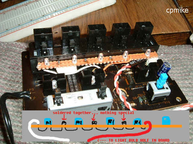 |
7 before working on this step, READ STEP 8, then come back. this is just a pic of how i mounted and wired the LEDs that light up the button
pictures. DO NOT DO IT THIS WAY- they later burned out - i was lazy and split the
12v connection between 4 LEDs at a time, providing 3v to each LED (ends up it was 14v, and
it overpowered and burnt out the LEDs) -you should wire each one SEPARATELY to the power
source, with a resistor on each.(tape up the resistors so they dont touch any other
connections) its safer. i connected to the 2 bulb holes for power. |
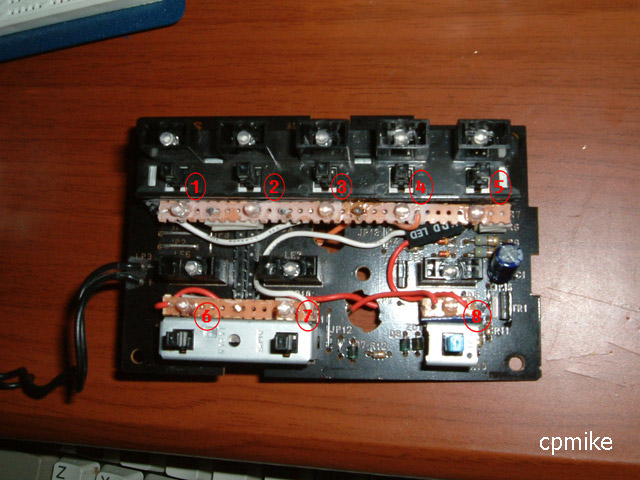 |
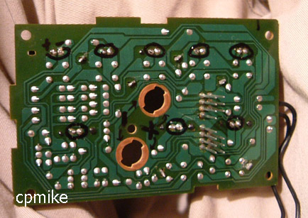
8 an overview pic of
the blue LEDs. I wires LEDs 1-4 in series together to the top bulb hole, and LEDs
5-8 to the bottom bulb hole. again, i say WIRE EACH ONE SEPARATELY, with its own
resistor!!!! |
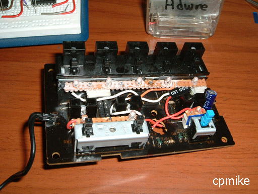 |
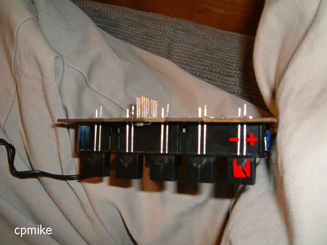
9 make sure no wires
or anything is in the way, and ur done with this part. leaving the two clear plastic prizms removed, reinstall the newly modded circuit board snugly, screw it down, and make sure it all fit back together. test-press each of the buttons a few times (they make make a snap when they re-seat themselves on the buttons for the for the first time) and make sure all are clicking correctly. |
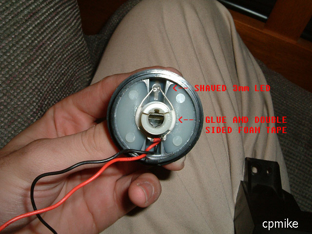 |
10 this is the back of the heater knob. do this for both- bend the LED leads to hold the LED facing into the back of the indicator spot on the knob, hold it there with some double sided foam tape, and soak the tape in superglue to hold it permanently. |
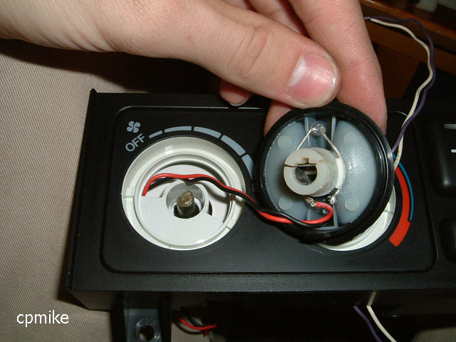 |
11 u can carefully peel off the black plastic cover from the white housing (the one that has the "off -----" and red/blue indicators on it, its just stuck on with a little glue) and pull out the white housing so u can run the wire easier, but this is how i ran the power wires for the knob LED. in the background u can see i did the other knob the same way, with the purple and white wires. with the wires thru to the other side, pop the knob on and make sure it turns without getting snagged (might take a couple removals and rerouting of wires to get it working well). |
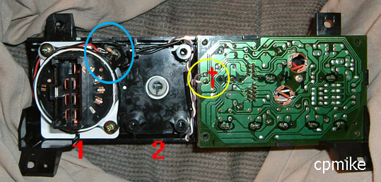 |
12 from the back, wire a resistor to each of the knob LEDs. the blue circle is where i wired knob #1's LED (to the back of the bulb socket) and i soldered a connection to the yellow circle for knob #2's LED. (+) and (-) are marked- to find the polarity of the wires at the bulb, ur gonna need match the wires with the marked + and -, and follow them to the bulb. good luck, and send me pics of your completed project! (get me on aim at cpm1xe and ill send u my email address) |
